So. A really… really… long time ago, I posted a method for mapping an icosahedral map of the sort that RPGs like Traveller are so enamored of, to a sphere in a 3d app. Similar projections were used by many science fiction role-playing games, such as 2300AD, GURPS Space and Space Opera.
Even back in those days of hoary antiquity I was looking for a means to map that surface onto an equirectangular map(plate carée, geographic or latlong for the technical). Given the prevalence of apps like G.Projector and Flex Projector, both of which require equirectangular maps as input, this was very desirable. Even the Flexify filter, with its many available input projections, chokes on most interrupted projections on input.
At long last I have found a way to convert icomaps into equirectangular projection.
This isn’t just useful for getting old science fiction RPG maps into a more usable projection. Having seen how these icomaps look projected back onto globes, I have to say this is a dandy little projection for drawing new maps in. Distortion is surprisingly limited. In the hand-drawn map that I am going to use to demonstrate this technique I placed the island of Korsland very near the north pole. In spite of that it has no noticeable pinching. That is an awesome for anyone who wants to draw a decent map of an imaginary world. The polar-pinch problem is common for maps drawn on the flat and very difficult to eradicate, but it really isn’t much of a problem with the icomap projection.
This method could also be used to derive a flat map from a texture painted in Blender with Texture Paint or noise effects. A last possibility, if one had an excellent grasp of povray scripting, would be to create maps from scripted combinations of noise in povray.
Looking at the Wikipedia, I found this page on Tissot Indicatrices. Included on that page was the povray source code used to generate the templates. I puzzled at this, then I realized the magic of the spherical camera.
Unfortunately, It took some trial and error to figure out how to export a uv-mapped object to povray. Wings3D exports to povray, but the uv-mapping seems to be lost. I finally figured out how to get it to render. I’ll go over it again, here.
This can be done entirely with free apps. I used Photoshop, but everything that needs to be done here can be done just fine in the GIMP. There are apparently several implementations of povray; I’m using MegaPOV, myself ’cause it comes pre-compiled for the mac. You’ll also need Wings3D.
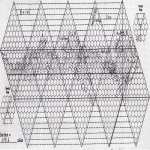
I have already successfully used this method to reproject maps of Regina from the World Builder’s Handbook by Digest Book Publications and Unnight from the GURPS Space worldbook of the same name by Steve Jackson Games. I wanted to use something I, myself owned and created. Since I started doing cartography in a serious way, I haven’t really used the icomap method very often. I knew that if I drew things out in equirectangular projection, I had a lot of apps that could readily reproject into a wide variety of other projections. I could also readily use it in 3D apps to create pictures as from space. I do have a few very old maps I made in my youth. To avoid getting into disputes about copyright law(a very popular subject on the net), I decided to use one of my own icomaps for this demonstration. For private use, it should be perfectly acceptable to use proprietary imagery in this manner, and the public exhibition of derivative works is… debatable. Private exhibition of derivative works should be completely kosher.
The map I’m using today was based very loosely on the map of Craw created by J. Andrew Keith for “A Referee’s Guide to Planetbuilding,” as found on page 25 of “The Best of the JTAS,” Volume 3. There are some significant differences, and the original was, oddly enough, in an equirectangular projection. I’ll call it Wark.
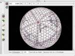
To start, let’s open Wings3D. To create our icosahedron, we’ll right-click somewhere on the screen and select “Icoshedron” from the menu. Now click somewhere on the icosahedron and press the B button to select the body. Now right click on the body and select “.UV Mapping.” from the menu.
You can control the view by clicking the middle mouse button and moving the mouse around to rotate. Hold down the middle mouse button and drag to dolly the view. Hit the left mouse button to get out of view control, when you’re happy about the view.
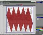
In the AutoUV Segmenting window, look at the top of the icosahedron. Hit the E button to select edges and click on the five edges around the north pole. Now look at the bottom and select the five edges around the south pole. Select one edge on the midsection of the body to connect one of the five selected edges in the north to one of the five selected edges in the south. Once you have these eleven edges selected, right click somewhere on the segmenting window and select “Mark Edges for Cut” from the menu. Now right click again and select “Continue”, now select “Unfolding.”
You’ll find in the AutoUV window that, if you have the triangles selected, a right click gives you a menu that includes the options, “Move,” “Scale,” and “Rotate.” Use these to move, scale and rotate the triangles are arranged horizontally, in roughly the orientation of your icomap and scaled so that the pretty nearly fill the square. Don’t worry too much about getting it perfect. We’ll adjust later.
Now right click again and select “Create Texture.” For Size, go with the biggest possible(2048×2048), and for Render select “Background” for 0, “Draw Edges” for 1, and “None” for 2. Hit OK.
In the Outliner window on the right of the screen, click on the checkerboard next to an item that says something like “icosahedron1_auv.” The number may vary. Now right click and select “Make External.” Pick out the location where you want to save the image and click Save.
Now in your favorite image editing app, open the image with the scanned map. You’ll want to scale this to match the texture resolution.
In Photoshop select the menu Image>Image Size…, uncheck “Constrain Proportions”, check “Resample Image:” and select Bicubic Sharper from the pop-down menu if your original map is smaller on any dimension than the texture resolution. Since the texture is 2048×2048 pixels, that is the Width and Height we want to set this image. The Document size stuff is irrelevant to our purposes. Click OK. Now the image is rescaled.
In gimp, select the menu Image>Scale Image…, click on the chain icon to unconstrain proportions, set Width and Height to 2048 pixels. Choose the Sinc(Lanczos 3) interpolation. Click Scale. Now the image is rescaled.
Now save your rescaled image in bmp format under the same name as the texture image, so as to replace it. For instance “icosahedron1_auv.bmp.”
Back in Wings3D, select the texture image once more. Right click and select “Refresh.” Give it a moment to load and you will find your icosahedron now has the map image projected on its surface. Sort of. Chances are things don’t quite line up. Now we fix that problem.
Let’s go back to the AutoUV window. Now hit the V key for vertex selection mode. For the sake of sanity, hit the spacebar to deselect all the vertices. As necessary, click vertices and drag them to the appropriate triangle corners. Selection is sticky, so if you want to select one vertex at a time(you will), hit the spacebar to deselect before selecting another vertex. To center the view on your vertex click on the AutoUV window menubar View>Highlight Aim, or just click the A key(which is much simpler). Zoom in using the scroll wheel. You’ll find that the same controls work in the 3d view and elsewhere. To move the selected vertex/vertices right click and select “Move.” You’ll probably want to “Free” move. Once you have all the vertices in the appropriate corners, have a look at the 3d view in the Geometry window. This should look much better now.
Once you get it looking satisfactory, something of a judgement call(if you’re satisfied, it’s satisfactory) save the icosahedron. Now, just as an experiment, select all twenty faces in the 3d view of the Geometry window. A short way to select all faces is to hit the B key to select the entire icosahedron, then hit the F key to change to face select mode. Now right click and select “Smooth from the menu, or just tap the S key. Repeat till you have about 960 faces. The next smooth after that increases abruptly to about 3840, which may be desirable, but for most purposes 960 faces looks pretty darn spherical. Even 240 faces might be sufficient for distant views and 3840 might need smoothing on extreme closeup. Not that the current texture is terribly suited to extreme closeup viewing. This ends our use of the eye candy, here. For the rest of this tutorial, we’ll be working with the straight icosahedron. Smoothing works for most purposes, and exports beautifully to the Wavefront OBJ format, but smoothing seems to break uv-mapping on povray export. Doesn’t matter, ’cause I think the geometry will still be perfect on the spherical projection.
Reload the uv-mapped icosahedron you saved earlier, and select the menu File>Export>Pov-Ray (.pov), making sure you click the little rectangle at the end. Under Camera, enter a Width of 2048 and a Height of 1024. Move the pull-down menu next to Camera from “Perspective,” to, “Spherical.” Click OK to export.
Now open your saved pov-file in MegaPov or your selected povray implementation. This needs some alterations. First, use your image editing app to save the texture file as a png.
You can try rendering, but it will likely fail.
First, comment out, “#include “rad_def.inc”.” Now comment out the entire “global” declaration. Change the camera_location to <0,0,0>.
In the camera block comment out the lines beginning with right, up, angle and sky. Change the look_at coordinates to <0,0,0>.
Comment out the light_source block.
In the texture block, add uv_mapping as the new first line.
Replace everything inside the pigment block with
image_map {
png “icosahedron_auv.png”
}
In the finish block change the ambient rgb vector to <1,1,1>. This will brighten up the rendered image a bit…
The parameters, as I set them are available for your perusal here.
Now you should get a successful rendering. If the image isn’t saving in
MegaPOV, go to Window>Render Preferences. If the pull-down menu under
Output File Options says “Don’t Save Image,” pull that down to “PNG.” Now try to render again. Now you should have an image you can open in Photoshop or gimp.
Last time I did this, I had to flip the canvas vertically because of mirroring, this time I had to flip horizontally. I’m not sure what was different, but if you examine the original icomap and compare to the reprojected version rendered in povray you should be able to figure out which way to go.
In Photoshop, you can flip the image by selecting Image>Image Rotation>Flip Canvas Horizontal(or vertical, if your image is upside down). I then used Filter>Other>Offset… to center my continents. This should only be a horizontal move, with the vertical move always set to zero.
In gimp, you can flip the image by selecting Image>Transform>Flip Horizontally(or vertically, if your image is upside down). I then used Layer>Transform>Offset to center my continents. This took a bit of trial and error, as the offset isn’t shown until you commit by hitting Offset. This should
only be a horizontal move, with the vertical move always set to zero.
When done save your map image. You can now import this image into gplates, Flex Projector, G.Projector or, with a suitable pgw file, GRASS or QGIS. If you have Flexify, you can also manipulate the projection in Photoshop.

This is what Wark looks like in gplates. Over the north pole, with most of the significant inhabited regions in view.
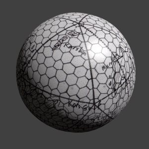
By the third time I did this, it took me about eight minutes to do the uv-mapping. Nicely. The povray portion of the exercise, including export from Wings3D, editing the script, rendering and flip and image editing took less than six minutes. It took about fifteen minutes to set up the parameters for the Blender beauty shot at the top of this page.
Thank you for reading,
The Astrographer


Pingback: On a Possible Method for Forcing Icosahedral Maps onto the Equirectangular Projection
Is there a way to go backwards? I need to turn an equirectangular map into an icosahedral projection.
That’s pretty easy. If you have Photoshop and still have a pile of money, Flaming Pear Flexify definitely has an “icomap” projection. I think it also has Bucky Fuller’s Dymaxion projection. If you have Windows or anything that can run WINE(like my Mac😃), Joe Slayton’s Wilbur has a filter that projects to a fairly standard icosahedral format. That one’s free. Flex Projector and G.Projector do NOT have an option to project to an icosahedral format(just checked).
Being free and pretty widely available, Wilbur would have to be my top recommendation.
You mentioned that “I posted a method for mapping an icosahedral map of the sort that RPGs like Traveller are so enamored of, to a sphere in a 3d app.” – I’m trying to do this right now ( https://i.imgur.com/rkzVMuC.png ) and haven’t quite come to grips with the problem. Can you repost your method – not the technique you use here but the math (e.g., verticies of hex (2,6) are the following latitude/longitude coordinates)
Yeah. I could probably figure out the mesh vertices if I sat down with one of my old textbooks and dredged up math classes from ten years ago, but it would be a struggle. It would definitely need to be a priority thing for me to do, ’cause I’m pretty sure that’s all I’d be doing for awhile.
So, at least for the time being, this isn’t really going to be happening. Sorry about that.
Pingback: Using Blender to Bake Icosahedral Maps | Astrographer
This is really cool, thanks for sharing it. Is there a way to increase the resolution of the pov-ray output?
I’m not too skilled with PovRay, and it looks like setting the resolution is less than simple in PovRay, but I did find this question on Stack Overflow(https://stackoverflow.com/questions/20043209/pov-ray-setting-output-resolution-or-width-heigh-ratio-within-the-script). Apparently, you change some settings in the “camera” section.
camera{
…
right $ImageWidth / $ImageHeight * x
…
}
replacing $ImageWidth with your desired image width and $ImageHeight with your desired image height. The ‘right’ command I commented out would apparently set the image to 320×240, for example.
I haven’t tried this out yet, but let me know how it works! Since I figured out how to do this in Blender… which apparently I never posted(not to self: write a post on doing this entirely in Blender)… I haven’t used PovRay much.
I banged my head against a wall with this one then looked up and saw a drop down with resolutions on it (doh!) but to get higher resolutions you have to write them into the ini file
Oh well. I was hoping we didn’t need to touch that.
I’ve been wrapping the output image around the google earth globe but google earth limits overlay images to 10mb. I been experimenting at subdividing the icosahedron into 5 segments so I could have 5 x 10mb images but all i get is a black image .. would you have any ideas on how to do this?
Geocart is supposedly adding a universal polyhedral solid projection. This would make all of the above quite easy. I do highly recommend this program for projection conversion. Flexify is also great. Together they are amazing!
I will have to check that out. I prefer to use open source when possible, except for Photoshop which I’m starting to shy away from.